Repair of columns in existing buildings and bridges is a challenging task. In many structures such as bridges, parking garages, ports and piers, mines, etc. columns corrode and require repair. In other cases, column jacketing is used as a technique to strengthen existing columns by adding a shell of reinforced concrete around the column. The latter is gaining popularity in seismic upgrade of structures and the ACI Committee 369 on Seismic Repair and Rehabilitation is currently developing guidelines for such applications.
The forming of existing columns is a difficult task. The existing floor and beams above prevent the use of conventional disposable cardboard tubes because they cannot be slipped over the column. The contractor is faced with assembling a form consisting of many segments around the host column. Because these forms offer virtually no resistance to the lateral pressure of the freshly cast concrete, the segments must be tied externally with bolts, clamps and the like. These forms can become very heavy and add significant time and expense to the project. The problem is especially arduous when the columns are not easily accessible.
This paper describes a recently developed product by the author that can overcome many of the above shortcomings.
FRP LAMINATE FORM
The new product is made of Fiber Reinforced Polymer (FRP). Using a special equipment, glass fibers are impregnated with vinyl ester resin and subjected to heat and pressure to make very thin laminates. For brevity, the product will be referred to as FRP Laminate Form (FLF) in this paper. The laminates have a uniform thickness that varies from 0.045 to 0.075 in. (1.1-1.9 mm) depending on the product style.
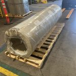
FLF is manufactured in rolls up to 102-in. (2590 mm) wide. A typical roll may include 500 feet (152 m) of FLF (Fig. 1). The laminates weigh between 0.31 to 0.51 lb/ft2 (1.5-2.5 kg/m2 ). The lightweight allows for easy handling. The mechanical properties of the laminates and the applicable ASTM Standards are listed in Table 1. The unique design of the laminate provides a perfect balance between a smooth finish surface and enough friction to prevent sliding of the surfaces.
HOW TO INSTALL FLF
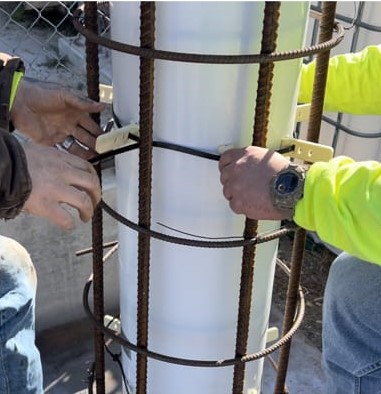
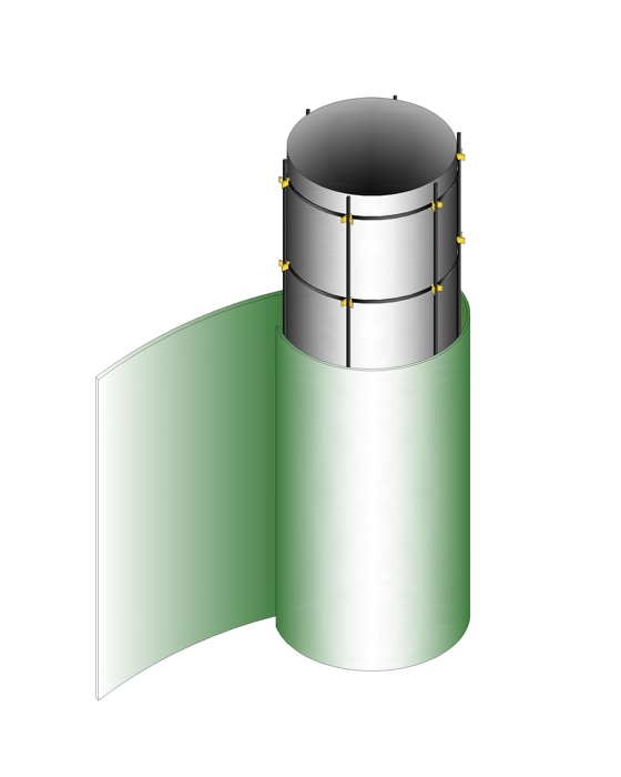
The behavior of FLF is based on principles of belt friction. Various shape and size spacers are available from QuakeWrap, Inc. as shown in Fig. 1. To repair a column, for example, these spacers can be threaded through a zip-tie and secured tightly around the column. They serve to hold the reinforcing bars in place, and to provide the desired standoff distance, i.e. the annular space, between the FLF and the exterior face of the column (Fig. 2).
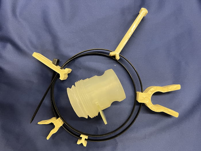
and grout injection port
| Property | US Customary |
| Flexural strength (ASTM-D790) | 1.91×10⁴ psi |
| Flexural modulus (ASTM-D790) | 6.0×10⁶ psi |
| Tensile strength (ASTM-D638) | 1.0×10⁴ psi |
| Tensile modulus (ASTM-D638) | 5.2×10⁵ psi |
| Izod impact (ASTM-D256) | 4.5 ft-lb/in. notched |
| Coeff. of Linear Thermal Expansion (ASTM-D696) | 1.7×10⁻⁵ in./in./∘F |
| Water absorption / 24 hours (ASTM-D570) | 0.3% @77∘F |
| Coefficient of Static Friction | 0.18 |
wrapped around a deteriorated column
A piece of the laminate long enough to be wrapped 2-3 times around the column is cut from the roll of laminate and is tightly wrapped around the structure. A piece of duct tape can be used to secure the interior edge of the laminate to itself to prevent any cement paste getting between the layers. The free exterior end of the laminate can also be optionally secured with a few pieces of duct tape. Alternatively, a few pieces of string can be tied around the tube (Fig 3a) to maintain the size of the tube. Note that the duct tape or strings are not required to resist any loads from the internal pressure of the concrete.
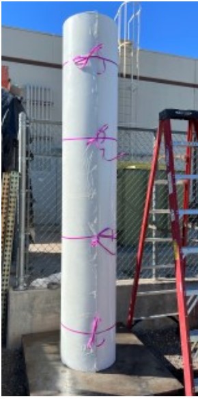
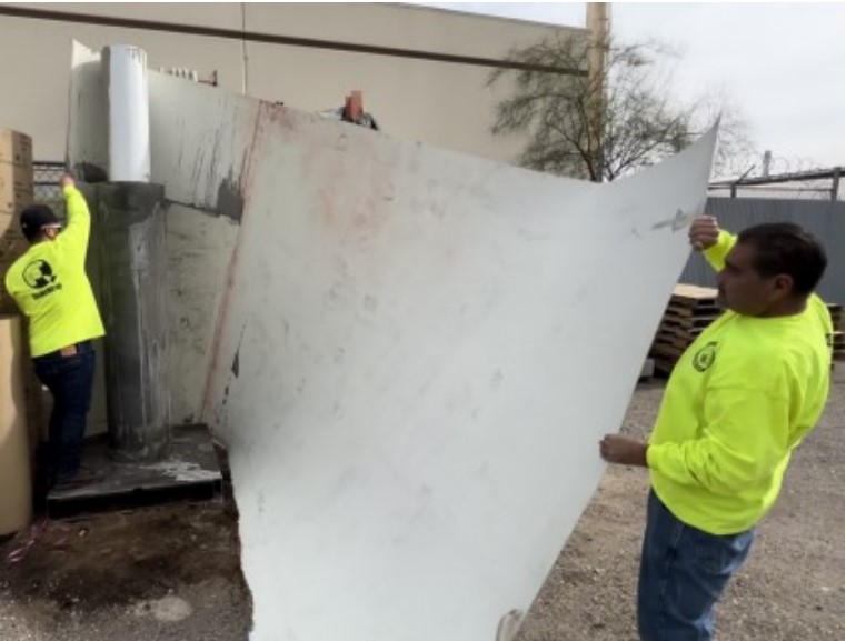
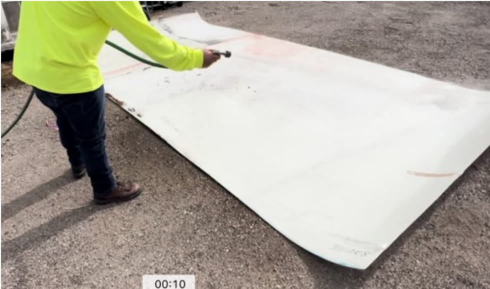
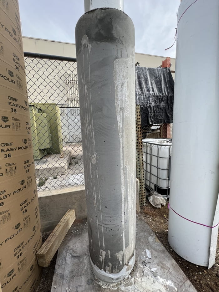
Once the FLF is in place, the concrete can be placed either using a hose and tremie method or by pumping it using the optional grout ports shown in Fig. 1. The latter will create a hole in the laminate that must be patched later and will ultimately limit the number of times the laminate can be used. After the concrete hardens, the strings are untied, and the laminate is removed (Fig. 3b). The laminate can be cleaned and washed (Fig. 3c) before it is coiled and stored away for future use to build a form of the same or different shape and size. Note the finished surface of the cast concrete that is very smooth (Fig. 3d) and free from unsightly spiral marks that are commonly left behind when cardboard tubes are used as forms.
As stated earlier, the behavior of this product is unique in that instead of using external clamps to hold the form together, the layers get pressed against one another due to the internal pressure of the grout. Referring to Fig. 4, if a tube of height H is filled with concrete, having a density , an internal hydrostatic pressure p= H is developed at the base of the form. This internal pressure shown with red arrows in Fig. 4, results in a friction force between all layers of the laminate that is shown with smaller blue arrows in that figure. The higher the pressure of the grout, the larger the friction force between the layers of the laminate. If the laminate is wrapped 3 times around itself, the external ties carry zero load. It is possible to use fewer layers. But in that case, stronger external ties such as ratchet straps must be used to resist some of the hydrostatic pressure of the concrete.
The laminates themselves are very strong and for most applications a single layer can resist the hoop stresses generated in the form. For example, assuming an 8-ft (2.4 m) high concrete placement with a unit weight of 145 lb/ft3 (23 kN/m3 ), the hydrostatic pressure at the base of the form will be 1160 psf (55.5 kPa). Assuming the diameter of the form is D=36 in. (914 mm), the tension force in a single layer of laminate will be T=145 lb (645 N). The 0.060in. (1.5 mm) thick laminate shown in Fig. 3, has a breaking strength of 600 lb/in. (105 N/mm) width of laminate which is significantly larger than the force T calculated above. This demonstrates that the construction of FLF with 2 or 3 layers of laminate is primarily aimed at enhancing the rigidity and stiffness of the tube since the tensile strength of a single layer of laminate is much more than what is needed to confine the hydrostatic pressure of the freshly placed concrete.
In the above demonstration, a circular column was formed around a damaged circular column. A major advantage of FLF is that by changing the size of the spacers, the flexible laminates allow construction of virtually any shape and size form in the field. Figure 4 shows a rectangular column cross section that can be enlarged to a larger rectangular column or an oval shape column, for example. The only limitation is that the radius of bend at the corners of a rectangular form must be larger than the allowable limit for the laminate. This radius is a function of the thickness of the laminate and is typically around 1 in. (25 mm).
PRESSURE TEST
To determine the adequacy of this system in resisting internal pressures, the following test was conducted. A 9.5- ft (2880 mm) long piece of a 0.06 in. (1.5 mm) thick laminate was cut from a long roll. This laminate was coiled to create a 3-ply tube with a diameter of 12 in. (305 mm) and a length of 102 in. (2590 mm). The free end of the laminate was secured to itself with a few short pieces of duct tape to make sure the tube diameter could not change freely.
An elongated balloon that is frequently used in internal repair of pipes was inserted inside the FLF. The balloon was connected to an air hose and gradually inflated to a pressure of 3300 psf (158 kPa). This is nearly 3 times higher than the pressure calculated in the above example and it is significantly higher than any anticipated pressure encountered in the field. The test was stopped at that pressure to avoid damage to the balloon. There was no sign of any damage in the FLF at the conclusion of the test.
SUSTAINABILITY
The FLF presented here has several unique features that contribute to making it an environmentally friendly product. One feature is the size of the FLF. With a single roll of laminate forms of any size can be built on site. The other is the adjustability of the shape of the form. As demonstrated in Fig. 4, the form can be shaped in rectangular, circular and an endless range of geometries in between. This flexibility can add significant value to many projects. Both of the above features contribute greatly to reduced transportation and storage space demand, cutting down on the number of trips to the supply stores.
The light weight of FLF eliminates the need for heavy lifting equipment on site that may be required for bulkier steel or timber forms. FLF is also fully water resistant, making its storage easier and allowing for challenging forming of submerged columns and piles. The smooth finish of FLF leaves no unsightly marks behind and eliminates the need for grinding of the finished surface.
The most significant advantage of FLF is the fact that the laminates can be used tens of times, producing forms of various shapes and sizes. The laminates have two identical sides or faces. On each side, there are two ends that can be put in contact with the concrete being placed. The only damage to the laminates can come from scratching where it meets concrete, Thus, if one end can be used 15 times, the entire laminate can be used 4 times as many or 60 uses!
Although this paper has focused on repair of existing columns, FLF can be used to build new columns as well. In those cases, an exterior frame may be used to help maintain the desired geometry of the column being cast (Fig. 5).
SUMMARY
A new type of form called FRP Laminate Form (FLF) has been presented. The form can be used for repair of existing columns or to form new columns. Among the advantages of the form are its ability to be used many times to create forms of virtually any shape and size. FLF reduces storage space and transportation cost significantly. It is fully water and rain resistant. All these features result in an environmentally sustainable product.
ACKNOWLEDGEMENT
The products and system presented in this paper are subject of multiple US Patents by the author. A video showing this product is available at: www.tinyurl.com/MoTubes

Mo Ehsani, PhD, PE, SE is President, QuakeWrap, Inc. and Centennial Emeritus Professor of Civil Engineering at the University of Arizona. He is a pioneer in the field of repair of structures with carbon FRP products and holds twenty patents in those technologies. He is also a registered general contractor in AZ and CA.
Mo@QuakeWrap.com (520)250-7020
