Abstract: Hollow steel tubes (HSS) are frequently used in electrical substations to support various equipment. Even though they are made of galvanized steel, poor details and/or deficiencies during the galvanizing process can result in corrosion due to the accumulation of moisture inside the base of these tubes. Unfortunately, the deterioration is usually concentrated at the base of the structure columns, where the stresses are at maximum. If repairs to the columns are not performed, the structural integrity is compromised.
This paper reports on the newly developed Fiber Reinforced Polymer (FRP) SuperLaminate™ and its use in repair of nearly sixty corrosion-damaged structures at two Tucson Electric Power (TEP) substations. The laminates are supplied in 4-ft wide rolls that are approximately 0.025 inch thick. The tensile strength of these laminates varies from 60,000 to 150,000 psi depending on whether they are constructed with glass or carbon fiber. In the field, the laminate is cut to the desired length and coated with an epoxy paste. The laminate is wrapped around the column a minimum of two wraps, creating a 4-ft tall cylindrical shell around the column. The annular space between the column and the shell is filled with concrete or grout. Additional reinforcing steel can be added in the annular space. The lower portion of the column is also filled with grout and a drain is added to prevent future accumulation of moisture. All repairs can be performed while the structure remains in service.
Introduction
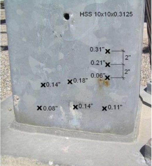
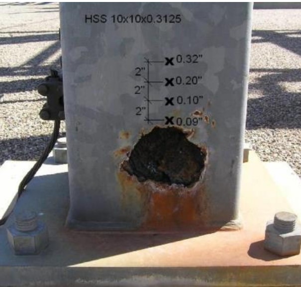
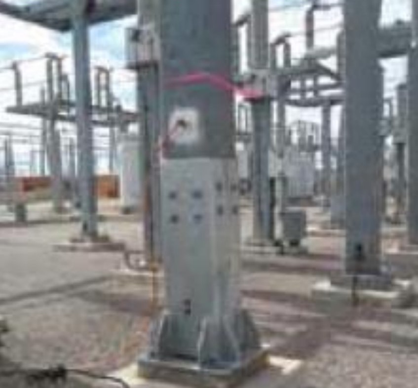
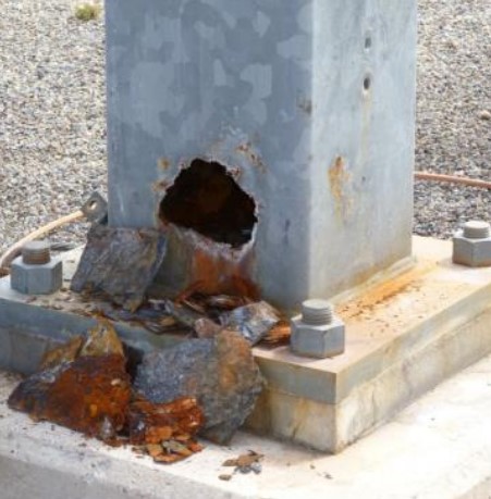
During an inspection at one of Tucson Electric Power’s substations, extensive corrosion was discovered on many of the substation support columns. Based on a visual inspection, it seemed that the corrosion had begun on the inside of the column wall meaning that the damage was potentially much worse than it appeared. An ultrasonic thickness gauge was used to determine the steel thickness adjacent to the visible damage. Measurements along the height of the columns indicated that the loss of wall thickness was more severe closer to the base of the column (Fig. 1). These investigations also revealed that in many cases the majority of the structural damage was on the inside of the square columns with little or no visible damage from the outside.
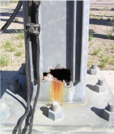
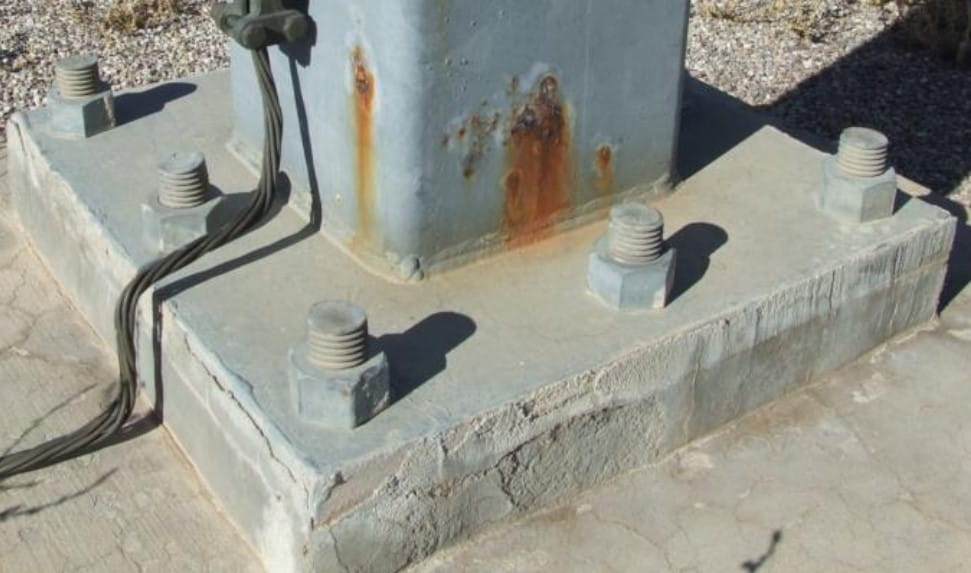
Since the majority of the structural damage was found to be on the inside of the square columns, it was concluded that the damage is most likely the result of deficiencies during the galvanizing process. It is likely that the acid bath was not properly drained from the columns during the prepping stage causing the inside of the square columns near the base not to be galvanized properly. In addition, during the installation of these columns, grout had been placed between the base plate and the foundation. This caused rainwater to be trapped inside the structure, which accelerated the corrosion process.
Earlier attempts to repair these columns included the use of steel collars as shown in Fig. 3. These collars had to be manufactured to fit the various size-damaged columns. The steel collars were bolted to the columns. An examination of these repaired columns showed that the corrosion process still continued inside the columns and the steel collars would hide the damage. In essence this would offer a false sense of security. These collars were also very heavy and difficult to install. They had to be custom designed to ensure that they could be installed considering the base configuration at each column and the supporting equipment that may be present.
These finding resulted in Tucson Electric Power seeking a better and more permanent solution for repair of these columns. Among the repair techniques, was a recently developed jacketing system that used Fiber Reinforced Polymer (FRP) products.
FRP Products for Repair of Structures
FRP products had been introduced in the late 1980s for repair and strengthening of existing structures (Ehsani & Saadatmanesh, 1990). The original technique for application of these is know as wet layup. In the wet layup process, rolls of fabric made with carbon or glass fabric are saturated with epoxy resin and are externally bonded to the surface of the structure requiring repair or strengthening. The materials cure in a few hours and become very strong in tension. Typical tensile strength for FRP products are 2-4 times that of steel. In addition to high tensile strength, the durability of these products that do not corrode and the ease of installation has made them very popular for repair and strengthening of civil infrastructure. Numerous buildings, bridges, pipelines, etc. have been retrofitted with these products worldwide. With the publication of design guidelines (ACI, 2008) it is fair to say that FRP is no longer an experimental product and it is rapidly gaining acceptance in the repair and retrofit industry.
The original form of FRP products that have been used to date are primarily. Fabrics offer the widest versatility in the field and are installed following a procedure commonly referred to as the wet layup method. This technique requires properly trained technicians to prepare the resin in the field, saturate the fabric with the resin and apply it to the structural member. Care must be taken to ensure that the fibers of the fabric are aligned in the correct direction and to remove all air bubbles before the fabric is cured. As a result, the quality of the finished FRP product is greatly influenced by the experience of the installation team. However, for these corrosion-damaged steel columns, FRP fabrics do not offer a suitable solution.
The author has recently developed a new type of FRP products called SuperLaminate™ that could be of great value for certain repairs such as these steel columns (Ehsani 2010).
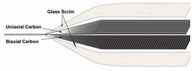
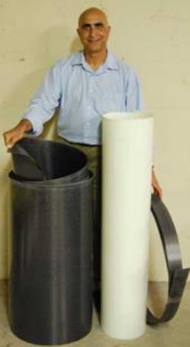
Super laminates are constructed with specially-designed equipment. Sheets of carbon or glass fabric up to 60 inches (1.5 m) wide are saturated with resin and passed through a press that applies uniform heat and pressure to produce the laminate (Figs. 4 and 5). Super laminates offer three major advantages over conventional laminates. First, by using a combination of unidirectional and/or biaxial fabrics, the laminate may provide strength in both longitudinal and transverse directions; this is a tremendous advantage that opens the door to many new applications (Table 1). Secondly, they are much thinner than conventional laminate strips; with a typical thickness of 0.025 inches (0.66 mm), they can are flexible enough to be formed into various shapes in the field. Lastly, the
| Type of Fiber | Thickness in. (mm) | Tensile Strength KSI (MPa) | Tensile Modulus KSI (MPa) |
| Carbon | 0.026 (0.66) | 156 (1,080) | 13,800 (95,500) |
| Carbon | 0.026 (0.66) | 101 (698) | 7,150 (49,280) |
| Glass | 0.026 (0.66) | 62 (431) | 3,500 (24,140) |
| Glass | 0.011 (0.28) | 49 (335) | 3,200 (22,060) |
number and pattern of the layers of fabrics can be adjusted to produce an endless array of customized products that can significantly save construction time and money.
Field Application
After investigating various alternatives, TEP chose the newly-developed super laminate FRP system for repair of the structures that could be implemented while the structure was in service and resulted in continuing system reliability. With proper oversight of safety personnel, the structures could be repaired without need for a costly outage.
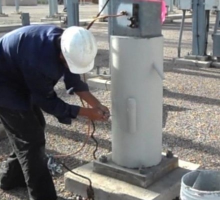
The repair of the columns with laminates was aimed at strengthening the lower 3 feet of the structures. First, the corroded material that had separated from the inside of the structure was removed and the column was cleaned of any rust (Fig. 6a).
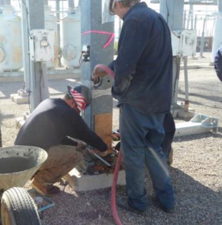
An access port about 3 inches in diameter was cut at an elevation of 33 inches from the base. The openings were temporarily sealed with plywood and clamps. A non-shrink high-strength grout was mixed and pumped into the structure from the access port (Fig. 6b). Four No. 5 U-shaped reinforcing bars were welded to the base plate; these bars were primarily for enhanced flexural capacity of the structure.
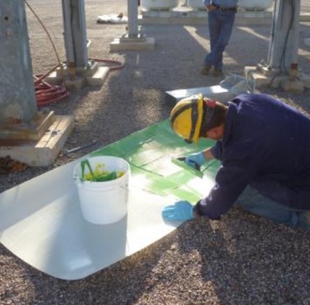
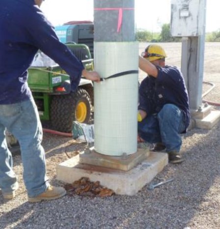
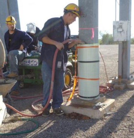
Due to its dielectric properties, a glass laminate with tensile strength of 62000 psi and thickness of 0.026 inch was used. A 3-foot wide x 8.5-foot long piece of laminate was used for each structure (Fig. 6c). A special two-component epoxy was mixed in the field and applied to an approximately 5-foot long section of the laminate. The mixed epoxy has a paste-like consistency and is applied with a trowel to a thickness of 20-30 mil (Fig. 6c). The laminate is then wrapped loosely around the structure to create a two-ply shell (Fig. 6d). The 8.5-foot length of the laminate allows creation of a two-ply 15-inch diameter shell with 8 inches of overlap beyond the starting point. At this stage, before the epoxy cures, ratchet straps must be used to hold the shell in the desired shape.
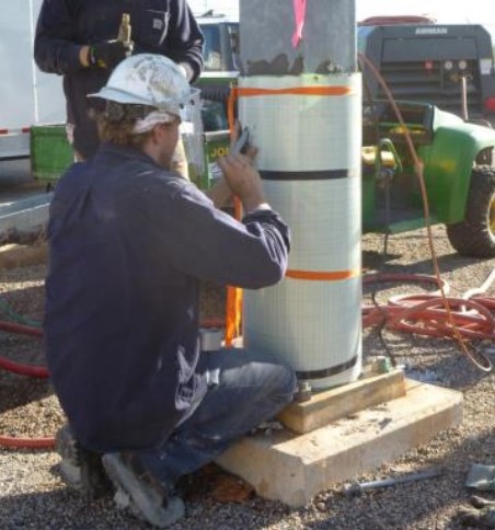
A 1-inch diameter PVC drain pipe was installed to make sure no rainwater will accumulate inside the structure (Fig. 6e). The bottom edge of the jacket was sealed with tape atop the base plate.
The annular space between the jacket and the steel column was also filled with the same non-shrink grout (Fig. 6f). Consolidation of the grout was completed with a small vibrator and the top of the grout was finished with a trowel. Before the grout sets, the hydrostatic pressure from the grout pushes the inner layer of the jacket outward against the outer layer and forces the two plies of the laminate to be tightly pressed against each other.
After several hours, the ratchet straps were removed and the exterior of the shell was painted with a UV-protecting coating (Fig. 7). All of these repairs were performed while the substation remained fully operational.
In this particular application, the intent was to restore the original capacity of the structure and therefore the foundation did not require any strengthening. In cases where a strengthening of the steel structure beyond its original capacity is desired, the capacity of the base plate and foundation must also be checked. It may be necessary to use anchor bolts to improve the overturning capacity of the foundation. Such an approach has been used recently to repair monopole towers that are used in cellular phone communication industry (PileMedic 2104).
Summary and Conclusion
The original repair of these structures that used steel collars allowed presence of moisture inside the columns which would lead to continued corrosion and degradation of the structure. The repaired structures using the FRP system now exceed the design strength capacity. This repair system eliminated the possibility of water accumulation inside the columns and the corrosion problem has been completely eliminated on the repaired Fig. 7 Completed repaired column structures. A further primary advantage of this repair system is that no electrical outage was required during the repair process.
Acknowledgements
The repair technique described in this article is protected by US Patent 8,650,831 and other pending U.S. and international patent applications.
References
ACI Committee 440. 2008. Guide for the Design and Construction of Externally Bonded FRP Systems for Strengthening Concrete Structures, American Concrete Institute, 440.2R-08.
Ehsani, M.R. and Saadatmanesh, H. (1990). “Fiber Composite Plates for Strengthening Bridge Beams,” Composite Structures, 15(4), 343-355.
Ehsani, M. 2010. FRP Super Laminates: Transforming the Future of Repair and Retrofit with FRP,” Concrete International, ACI, 32(03): 49-53.
PileMedic. 2014. “Strengthening of Cell Phone Communication Towers with PileMedic®” , A video available on www.YouTube.com.
