Reinforced concrete columns in many older buildings may require strengthening. This need could arise from a variety of conditions. In warm and humid coastal regions and aggressive environments, the corrosion of reinforcing steel results in the loss of capacity of the columns. In other cases, poor quality control during the original construction may result in low compressive strength of the concrete and reduced capacity of the column. The author was personally involved with the retrofit of two such buildings in Florida, USA, where the concrete compressive strength was below 1500 psi (10.3 MPa), only a fraction of the strength specified in the design documents. Some of the investigations following the collapse of Champlain Towers in Surfside, FL, have also mentioned weak and “powder-like” concrete in the columns as a potential contributing factor to the failure. This article describes a method for enhancing both the axial and flexural capacity of such columns. Implementing the technique is relatively easy, leading to a fast and economical solution with minimal disruption to the occupants. An additional feature of the repair is its small footprint, which minimizes floor space loss due to such modifications.
Conventional Solution
The author introduced the concept of repair and strengthening of structures with fiber-reinforced polymer (FRP) products in the late 1980s.1 In that approach, known as a wet layup, sheets of carbon or glass fabric are saturated in the field with epoxy. They are bonded to the external surface of structural elements, such as beams, columns, or walls. Within several hours, the materials harden and the FRP strengthening serves as additional tension reinforcement that can contribute to the flexural and shear resistance of the host structure. The FRP fabrics wrapped around the column confine the concrete and can increase its compressive strength. This results in an increase in the axial capacity of the column. While the technique is efficient for circular columns, the gain in axial capacity for rectangular columns is limited. Because FRP cannot be easily extended through the floors, it is difficult to achieve significant axial and flexural enhancement of columns with these products. Furthermore, externally bonded FRP does not increase the stiffness of the column that much. These shortcomings can be overcome using FRP laminates.
FRP Laminates
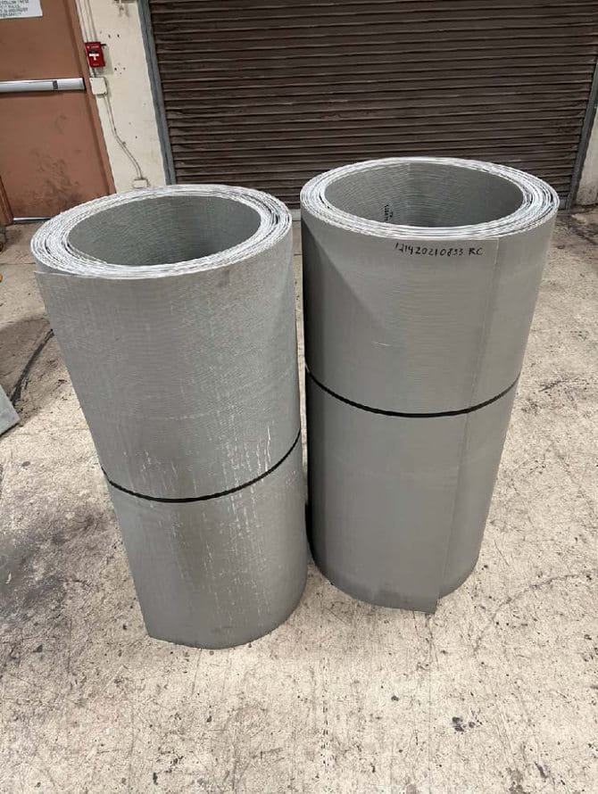
Over a decade ago, a new type of FRP laminate (PileMedic®, shown in Fig. 1) was introduced for applications in strengthening columns or piles and pipes.2 These laminates are produced with specially designed equipment where sheets of carbon or glass fabric up to 9 ft (2.7 m) wide are saturated with resin and passed through a press that applies uniform heat and pressure.
The laminates offer several advantages compared to the fabrics used in wet layup applications:
- Strength in both longitudinal and transverse directions, with tensile strength up to 155 ksi (1070 MPa), by using a combination of unidirectional and/or biaxial fabrics;
- Can be made as thin as 0.03 in. (0.8 mm), which allows them to be bent around a corner with a radius of 2 in. (50 mm);
- Manufactured in plants under high quality control standards, which improves the quality of the finished product;
- Strength can be tested before installation, which assures the design engineer that the specified strength is met, eliminating delays for corrective actions;
- Repairs can be completed much faster in the field;
- The number and pattern of the layers of fabrics in the laminates can be adjusted to produce an endless array of customized products that can significantly save construction time and money;
- They are used to build a structural stay-in-place form around the column, creating an annular space that can be filled with concrete and reinforcing bars3 and providing shear reinforcement and confinement for the column; and
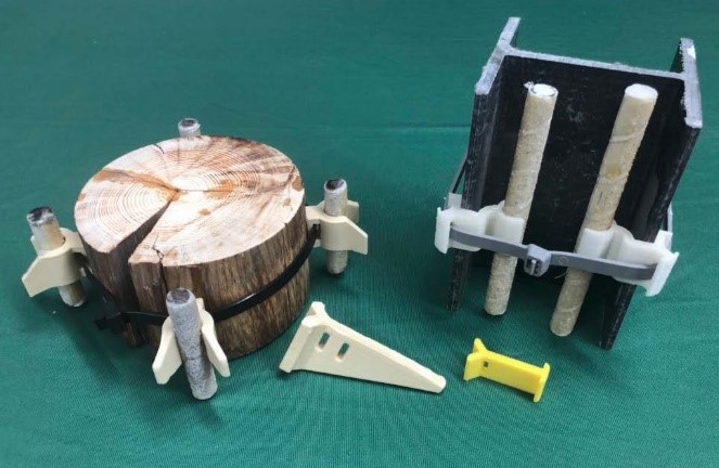
- Specially designed spacers4 are used to hold longitudinal reinforcing bars in place and to help create a shell around the column (Fig. 2).
Application
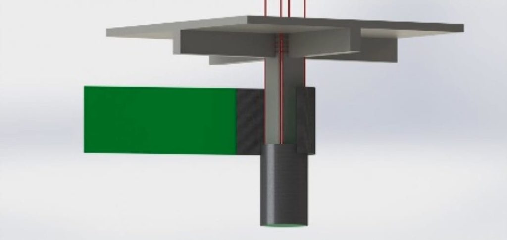
PileMedic laminates are supplied in 4 ft (1.2 m) wide rolls to any desired length (wider rolls are also available). Typical detail requires the laminate to be wrapped two complete times plus an 8 in. (200 mm) overlap around the column. The laminate is cut to the desired length, and an epoxy paste is applied; the laminate is wrapped around the column and bonded to itself to create a two-ply shell at a distance of 1 to 2 in. (25 to 50 mm) from the face of the column. Additional 4 ft laminates are similarly installed and overlap the previous shell by 3 to 4 in. (75 to 100 mm) to cover the full height of the column (Fig. 3). Finally, the annular space between the column and the PileMedic jacket is filled with concrete or grout using a pump or the tremie method.
Lateral ties
The jackets also act as supplementary steel ties, which is a shortcoming in many older or corrosion-damaged columns. Eliminating the need for ties around the longitudinal bars is a great advantage that results in easy installation.
Corrosion protection
The system provides an impervious jacket around the column that prevents the ingress of moisture and oxygen. By depriving the column of exposure to moisture, the corrosion rate is drastically reduced, resulting in the long service life of the repair.
Joint region
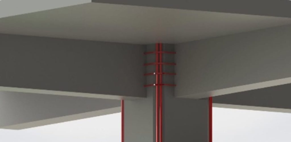
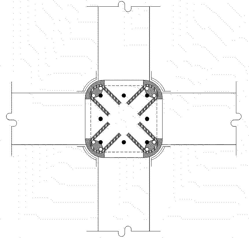
The retrofit of the frame, especially in seismic regions, requires attention to the beam-column joint region as well. One option is to epoxy anchor steel ties into the core of the column to provide support against buckling for the newly installed longitudinal column bars (Fig. 4). This region can subsequently be encased in concrete with additional reinforcement. Such enlargements are typically within the depth of the beam and can remain invisible above the ceiling. An earlier study demonstrated that as the flexural strength ratio increases, the required lateral ties in the joint region may be relaxed.5 Thus, the flexural strengthening of the column may result in easier retrofit for the joint.
Lower construction cost
The PileMedic retrofit solution has many inherent advantages that lead to cost savings. For example, the entire system comprises lightweight materials that can be taken to any floor of the building using passenger elevators. Handling of the laminates to wrap them around the column requires no heavy lifting of equipment. The adjustability of the jacket size in the field leads to a smaller footprint and eliminates construction delays due to shipping the wrong size formwork to the site. The strength of the laminate that eliminates steel ties results in faster and less costly repairs. The estimated cost to retrofit a typical column is well below $10,000.
Design Examples
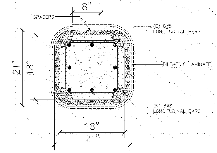
Two retrofit alternatives are presented here. In both cases, the corners of the column that do not include any reinforcing steel can be easily cut and removed to minimize the enlargement of the column and loss of floor space. Two new No. 8 (25 mm) bars can be placed at each corner, and these bars extend to the floor above through the slab. This increases the flexural capacity of the column to ensure a “strong- column/weak-beam” at that location. Plastic spacers are attached on the column to define the annular space.
Option 1
In this case, the 18 x 18 in. (460 x 460 mm) column is enlarged to a 21 x 21 in. (533 x 533 mm) column (Fig. 5(a)). A biaxial glass FRP laminate is used to create a two-ply shell around the column.
The minimal enlargement is sufficient to accommodate the eight new reinforcing bars being installed. The shell around the column is made with two plies of PileMedic glass laminate, which represents the minimum number of layers for such applications.
The interaction diagram for the retrofitted column is calculated and is shown in the solid red line in Fig. 6, assuming the grout strength is 4000 psi (27.6 MPa). The axial capacity of the column is increased by 51% from 1460 to 2215 kip (from 6500 to 9850 kN). The flexural capacity is also increased by 220% from 215 to 485 kip∙ft (from 291 to 657 kN∙m). Therefore, the flexural strength ratio for the retrofitted frame is
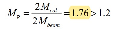
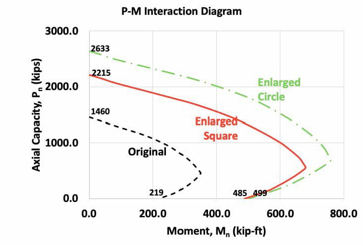
This is larger than the minimum value of 1.2 and ensures that any plastic deformations are concentrated at the beam ends.
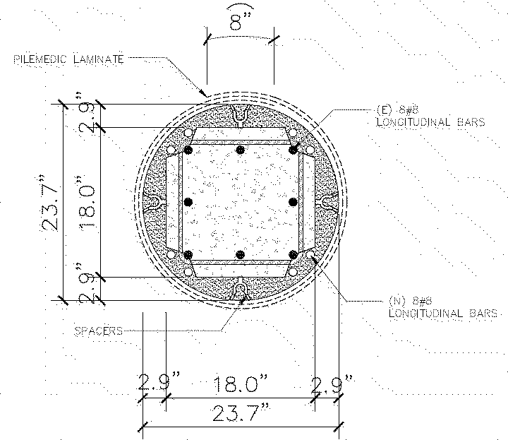
Option 2
If, in addition to flexural capacity enhancement, a greater increase in the axial capacity of the column is also desired, it’s best to alter the column into a circular section (Fig. 5(b)). Because confinement is a function of the stiffness of the jacket, a carbon laminate can be used instead of the glass laminate used previously. A circle with a diameter of 23.7 in. (600 mm) has the same area as the 21 x 21 in. column used in Option 1, that is, the footprint of the repair for both options is the same. However, the combination of circular geometry and wrapping with the stiffer and stronger carbon laminate results in an increase in the compressive strength of the original concrete and the newly placed concrete in the annular space. ACI 440R.2-176 provides guidelines for quantifying this strength gain and, for this example, the confined concrete reaches a compressive strength of 5150 psi (35.5 MPa).
| Retrofit | Option 1 | Option 2 |
| Laminate type | PLG14.13 | PLC150.10 |
| Laminate construction | Biaxial glass | Unidirectional carbon |
| Tensile strength, ksi | 28.7 | 156 |
| Tensile modulus, ksi | 2840 | 13,800 |
| No. of plies in wrap | 2 | 2 |
| Equivalent lateral tie | No. 4 Grade 40 at 3.7 in. | No. 4 Grade 40 at 1in. |
| Original column f”c, psi | 4000 | 4000 |
| Enlarged shape | 21 x 21 in. (square) | 23.7 in. (round) |
| Enlarged area, in.2 | 441 | 441 |
| Confined f”cc, psi | 4000 | 5150 |
| Pn, kip | 2215 | 2633 |
| Mn, kip-ft | 485 | 499 |
1 kip∙ft = 1.4 kN∙m
The compressive strength of concrete does not affect the flexural strength of the column significantly. In this case, the retrofitted column has a flexural capacity of Mn = 499 kip∙ft (676 kN∙m), which is slightly higher than in Option 1. However, as shown in the interaction diagram (Fig. 6), the axial capacity of the confined column increases greatly. In this case, an 80% increase from the original column and a 19% increase, when compared to Option 1 with a square shell with glass laminate, is achieved. Clearly, this option is preferred when the gain in axial capacity of the column is also desired. For example, this could be the preferred retrofit method when due to construction errors, the compressive strength in the column is lower than the specified value.
A summary of these retrofit alternatives is presented in Table 1.
Lateral Tiles
ACI 440.2R-17 provides environmental reduction factors for FRP based on the use conditions, such as exterior versus interior installation and the type of fibers used, carbon versus glass. Including these reduction factors, the glass laminate is equivalent to providing No. 4 Grade 40 (275 MPa) ties at a spacing of 3.7 in. (94 mm), while the carbon laminate is equivalent to No. 4 ties at a spacing of 1.0 in. (25 mm); refer to Table 1. In both cases, these values exceed what the current codes require.
Footprint
The footprint of the proposed retrofit is very small. In this example, the column cross-sectional area was increased by 36% for both the square and circular alternatives, while the flexural capacity of the column was more than doubled.
Field Application
Since the introduction of this system, many agencies have conducted independent tests to verify the efficacy of these laminates for a range of applications. These include a study funded by the National Science Foundation (NSF) and the California Department of Transportation (Caltrans) for fast repair of earthquake-damaged bridge piers, a study funded by the Nebraska Department of Roads for strengthening deteriorated timber bridge piles, and another funded by the Texas Department of Transportation for the repair of corrosion-damaged steel H-piles. The most significant investigation was a 3-year study by the U.S. Army Corps of Engineers, which resulted in the military selecting a laminated product to repair submerged piles worldwide. The U.S. Navy’s website reported that the product was used to repair concrete piles in Ukraine (www.tinyurl.com/PLM-UKR). The U.S. Army Corps of Engineers and the Federal Emergency Management Agency (FEMA) have also singled out these laminates as the selected product for repairing columns and piles that may be damaged in a disaster, including hurricane, earthquake, terrorism, and more in its 2013 Field Operations Guide.
References
- Saadatmanesh, H., and Ehsani, M.R., “Fiber Composite Plates Can Strengthen Beams,” Concrete International, V. 12, No. 3, Mar. 1990, pp. 65-71.
- Ehsani, M.R., “FRP Super Laminates,” Concrete International, V. 32, No. 3, Mar. 2010, pp. 49-53.
- Ehsani, M.R., “Reinforcement and Repair of Structural Columns,” U.S. Patent No. US 9,890,546 B2, Feb. 13, 2018, 13pp.
- Ehsani, M.R., “Spacers for Repair of Columns and Piles,” U.S. Patent No. US 10,808,412 B2, Oct. 20, 2020, 18pp.
- Ehsani, M.R., and Wight, J.K., “Confinement Steel Requirements for Connections in Ductile Frames,” Journal of Structural Engineering, ASCE, V. 116, No. 3, Mar. 1990, pp. 751-767.
- ACI Committee 440, “Guide for the Design and Construction of Externally Bonded FRP Systems for Strengthening Concrete Structures (ACI 440.2R-17),” American Concrete Institute, Farmington Hills, MI, 2017, 112 pp.
- Yang, Y.; Sneed, L.; Saiidi Saiidi, M.; Belarbi, A.; Ehsani, M.; and He, R., “Emergency Repair of an RC Bridge Column with Fractured Bars using Externally Bonded Prefabricated Thin CFRP Laminates and CFRP Strips,” Composite Structures, V. 133, Dec. 2015, pp. 727-738.
- Gull, J.H.; Mohammadi, A.; Taghinezhad, R.; and Azizinamini, A., “Experimental Evaluation of Repair Options for Timber Piles,” Transportation Research Record, V. 2481, No. 1, Jan. 2015, pp.124-131
- Dawood, M.; Karagah, H.; Shi, C.; Belarbi, A.; Vipulanandan., C.; Bae, S.-W.; and Lee, S., “Repair Systems for Deteriorated Bridge Piles: Final Report,” FHWA/TX-17/0-6731-1,Texas DOT, Austin, TX, , Apr. 1, 2017, 538 pp.
- Hammons, M.I; Strickler, J.S.; Murphy, J.W.; Rabalais, C.P.; Crane, C.K.; and Barela, C., “Pile Wrapping for Expedient Port Repair,” Draft Report, U.S. Army Corps of Engineers, Vicksburg, MS, Aug. 2018, 117 pp
- “Field Operations Guide,” seventh edition, U.S. Army Corps of Engineers, Vicksburg, MS, June 2013, pp. 4-4 to 4-5.
