The use of wireless communication has seen exponential growth in recent years. Not only is the number of customers relying on these services rapidly growing worldwide, but the amount of information being transmitted through these networks is also increasing. Whereas a decade ago mobile phones were used primarily for transmission of voice and text data, the trend has been towards use of images and video . These files are much larger in size, requiring faster networks to handle the heavier traffic.
The majority of telecommunication towers in the United States are steel latticed self -supporting/guyed structures or cantilevered pole s, referred to as “monopoles” in the telecommunication tower industry. In denser urban environments, shorter prestressed concrete spun poles have been utilized. These poles were typically designed for a limited amount of appurtenances such as a single antenna array on a small mounting frame at the top of the concrete pole for the original client.
In order to keep up with the changing needs and increasing demands on their networks as the carriers migrate from 3G to 4G technologies and beyond, these wireless service providers may need to substitute or augment their existing antenna array. In order to do so, a structural analysis considering the proposed change is first performed on the existing tower to verify that the structure would have adequate capacity. Current code requirements tend to be more demanding than when the pole was originally designed . Additionally, the proposed antennae sizes and weights have increased over the years as technologies have evolved to better support the wireless service providers’ customers. Because of these two factors, the pole may require structural upgrades to meet the higher demand from the proposed changes.
In parallel with this need for strengthening, there is a growing interest in the western states to seismically upgrade these towers. It is obvious that in the hours immediately following a large earthquake, cell phone communication is in high demand and the system must be designed to survive such an event. As an example , Los Angeles has recently introduced an ordinance requiring upgrading all cell phone towers to survive the pending ” big” earthquake .
While retrofitting steel telecommunication towers is quite common and various options exist, such as upgrading the size of existing members and bolting or welding additional steel to the structure, there are limited options to strengthen precast concrete poles.
An alternative to these options is presented in this article. The proposed alternative is a cost-effective solution for structurally retrofitting an existing precast pre-tensioned concrete pole that can be installed without taking the wireless carrier’s equipment off the air. Repairs can be completed within a reduced time frame compared to the other options and without significantly altering the overall appearance of the structure.
work space available at the base
Case Study
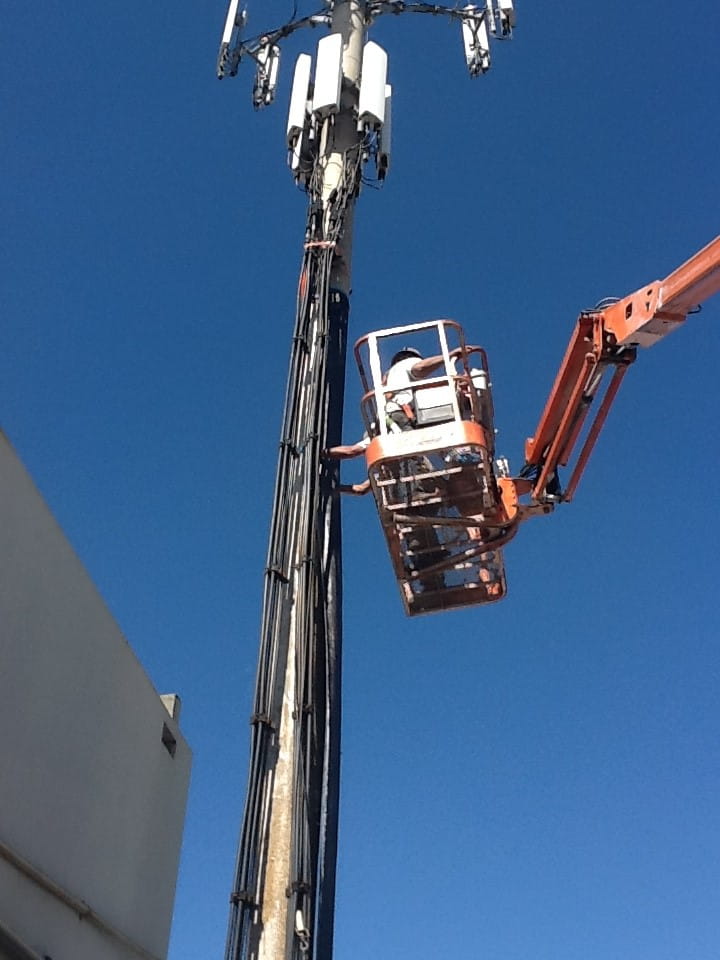
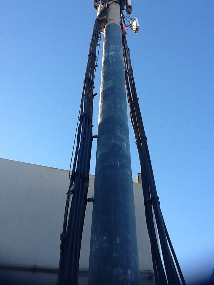
A 55-ft (16.8 m) tall hollow precast concrete cell phone pole located in Los Angeles (Fig.I) was originally designed and constructed in 1996. The prestressed concrete spun-cast pole had a constant outside diameter of 15.75 in (400 mm) with a wall thickness of 2¼ in (57 mm). Reinforcing steel is comprised of0.375 in (10 mm) diameter 250k (1112 kN) seven-wire strands. The structure is supported on a 36 in (914 mm) drilled pier foundation embedded 17 ft (5.2 m) deep.
Based on the code requirements at the time of design, prestressed concrete poles were typically designed for a single carrier level. Future proposed antennae additions coupled with code changes since the design can lead to the structure requiring additional capacity. Options for reinforcing these structures are limited and typically not cost feasible. The alternatives that were considered for this project are reviewed below.
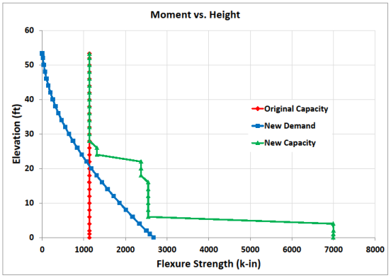
The original capacity of the pole was 1135 kip-in and remains constant throughout the entire height of the pole (Fig. 2). The pole was analyzed for all dead and live load effects, including wind and earthquake . The control ling new demand shown in Fig. 2 resulted in the lower 22 ft (6.7 m) of the pole being overstressed by various degrees . As such, the strength of the pole needed to be enhanced by nearly 136% at the base.
One option used on past projects requires guying the structure that presents technical hurdles as well as practical considerations. The introduction of guy wires will most likely require the tower owner to incur additional costs purchasing or leasing additional ground space in the vicinity of the tower in order to expand the site foot print to place the new guy anchorage points. The guy wires would also require additional ongoing maintenance and inspections.
A second option has been to build a steel tower, including new foundations , around the existing structure. This option is typically quite expensive and may be prohibited by the local permitting jurisdiction due to significant changes to the aesthetics of the original structure.
In some cases, a third option to remove and replace the structure may be considered. However, this alternative is typically not preferred due to the logistics, the required permitting process, cost considerations and the disruption of service to the wireless providers. Complicating all of these options is that typically there is minimal space to work within the existing congested site compound with numerous obstructions.
The fourth option involved the use of Fiber Reinforced Polymer (FRP) that is described in more detail below.
The original capacity of the pole was 1135 kip-in. and remains constant throughout the entire height of the pole (Fig. 2). The pole was analyzed for all dead and live load effects, including wind and earthquake. The controlling new demand is shown in Fig. 2. The lower 22 feet of the pole were overstressed by various degrees. At the base, the strength of the pole had to be enhanced by nearly 136%.
One option used on past projects requires guying the structure that presents technical hurdles as well as practical considerations. The introduction of guy wires will most likely require the tower owner to incur additional costs purchasing or leasing additional ground space in the vicinity of the tower in order to expand the site foot print to place the new guy anchorage points. The guy wires would also require additional ongoing maintenance and inspections.
A second option has been to build a steel tower, including new foundations, around the existing structure. This option is typically quite expensive and may be prohibited by the local permitting jurisdiction due to significant changes to the aesthetics of the original structure.
In some cases a third option to remove and replace the structure may be considered. However, this alternative is typically not preferred due to the logistics, the required permitting process, cost considerations and the disruption of service to the wireless providers. Complicating all these options is the fact that typically there is minimal space to work within the existing congested site compound with numerous obstructions. The fourth option involved the use of FRP that is described in more detail below.
FRP Alternative
Among the options considered, the use of FRP offered the most viable solution (Fig. 3). The technique offered the flexibility to readily change the strength of the pole along the height. A close examination of the stresses revealed that both compressive and tensile stresses in the pole exceeded the allowable limits under the new loads. FRP products have high tensile strength and can address the shortcomings of the pole easily. However, the compressive strength of FRP is significantly lower than its tensile strength. In most retrofit projects, it is not uncommon to ignore the compressive strength of the FRP. This meant that the thickness of the concrete wall of the pole had to be increased by the addition of conventional concrete or grout to lower the compressive stresses below allowable limits.
Tension reinforcement for the pole was provided by bonding unidirectional carbon fabrics to the exterior surface of the pole. The carbon fabric used for this project was supplied in 24 in (610 mm) wide rolls and has a tensile strength of over 6 kips (27 kN) per 1 inch (25 mm) width of fabric. The fabric could also be cut into narrower bands for ease of installation without any adverse effect on its strength.
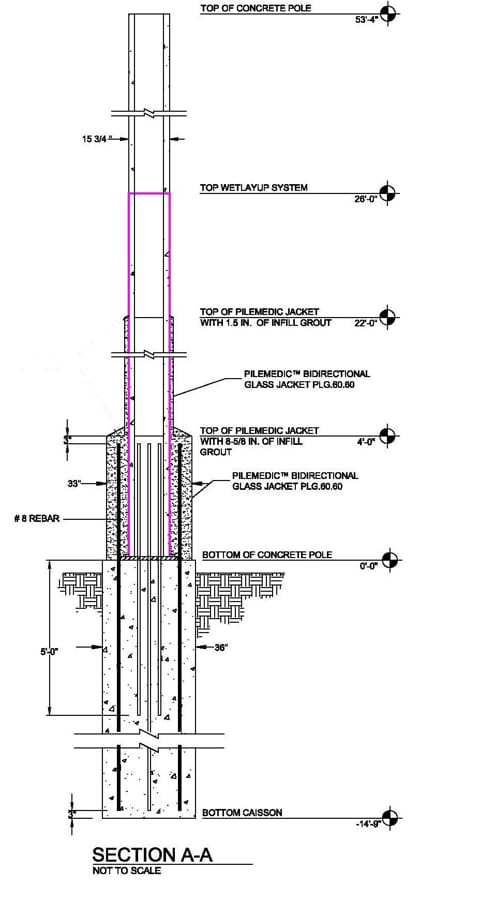
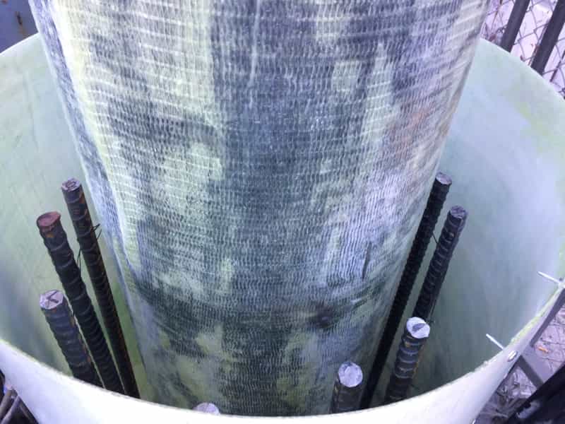
Based on the required strength , three (3) layers of carbon fabric saturated with epoxy were applied on the lower 16 ft (4.9 m) of the pole. Two (2) layers were sufficient for elevation 16 to 26 ft (4.9 to 7.9 m). Elevations above 26 ft (7.9 m) required no strengthening. For confinement and to eliminate any interference with the antennae signals, 2 ft (0.6 m) wide bands of a unidirectional glass fabric saturated with epoxy were wrapped in the hoop direction over all carbon fabric (Fig. 4) for elevations O to 26 ft (7.9 m).
As mentioned earlier, the 2¼ in (57 mm) thick wall of the pole was over stressed in compression. Therefore, the pole wall thickness had to be increased to meet the allowable compressive stresses. This increase in thickness can be different along the height of the pole, requiring a form work or jacket whose diameter could be easily adjusted in the field. For this project, an increase in thickness of 1½ in (38 mm) for heights Oto 22 ft (6.7 m) was sufficient. For elevations of 22 to 26 ft (6.7 to 7.9 m), no increase in thickness was required and only FRP fabric was sufficient for increased tensile strength.
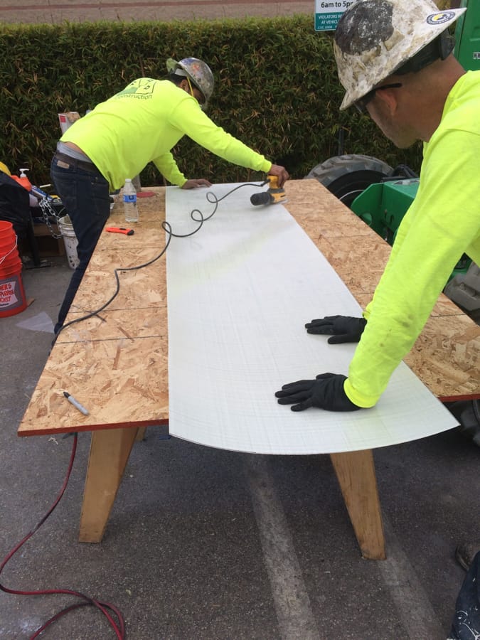
A special FRP laminate offered an economical solution for this application. The laminates are manufactured in the plant by saturating rolls of fabric with resin and running them through a special press that applies heat and pressure, resulting in 4 ft (1.2 m) wide rolls with a thickness as little as 0.01 in (0.25 mm). The relatively large width and small thickness of the laminates makes their manufacturing unique and challenging. The thin laminates (Fig. 5) are flexible and could be readily wrapped around the pole in the field to create a stay-in-place form that can be filled with grout or resin. The properties of the laminates are listed in Table 1. Depending on their composition, the laminates offer reinforcement in one or two directions.
| Unidirectional Carbon | Biaxial Carbon | Biaxial Glass I | Biaxial Glass II | |
| Thickness, in (mm) | 0.026 (0.66) | 0.026 (0.66) | 0.026 (0.66) | 0.010 (0.25) |
| Longitudinal Direction: | ||||
| Tensile Strength, ksi | 156 | 101 | 62 | 49 |
| Tensile Modulus, ksi | 13,800 | 7,150 | 3,500 | 3,200 |
| Traverse Direction: | ||||
| Tensile Strength, ksi | 9 | 64 | 60 | 49 |
| Tensile Modulus, ksi | 1,190 | 2,940 | 3,650 | 3,200 |
For this project, the biaxial glass laminate with a thickness of 0.026 in (0.66 mm) was used. For the region covering the height of 4 to 22 ft (1.2 to 6.7 m), these laminates were coated with an epoxy paste and wrapped around the pole to create a two-ply shell. At this stage, the shell is not bonded to the pole and it is free to be moved up and down. Temporary l½ in (38 mm) thick spacers , such as a PVC pipe, were attached to the pole surface to facilitate the wrapping of the laminates with the necessary annular space. The structural shell created in this fashion provides the equivalent of No. 4 Grade 40 ties at a spacing of 2½ in (64 mm) along the pole. The shell also offers a tensile resistance similar to No. 4 Grade 40 steel reinforcing bars distributed at 2½ in (64 mm) spacing around the pole. For this project, these contributions were conservatively ignored. The selection of glass over carbon laminates was based on the electrical insulation properties of the former.
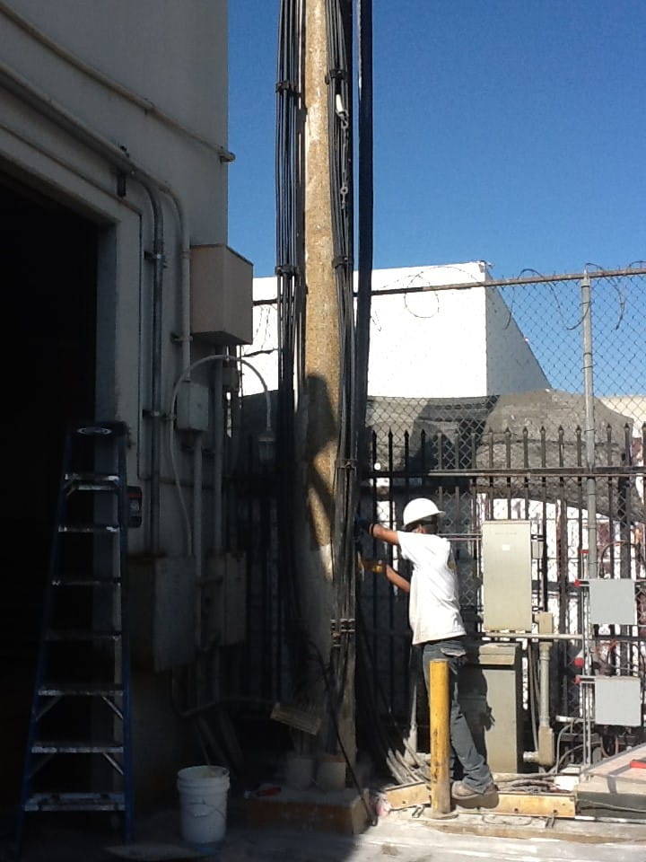
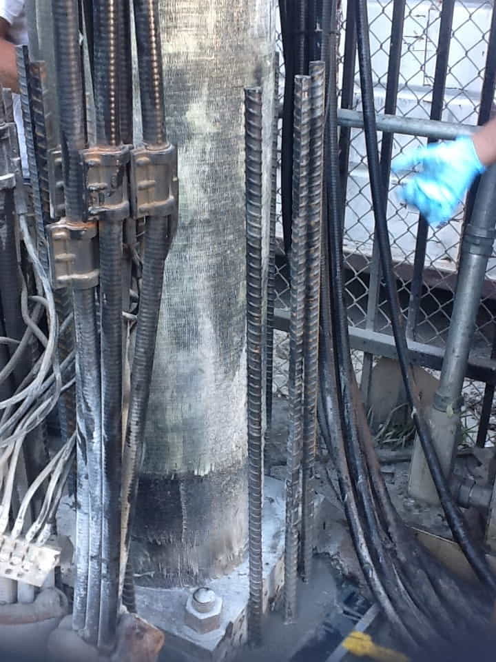
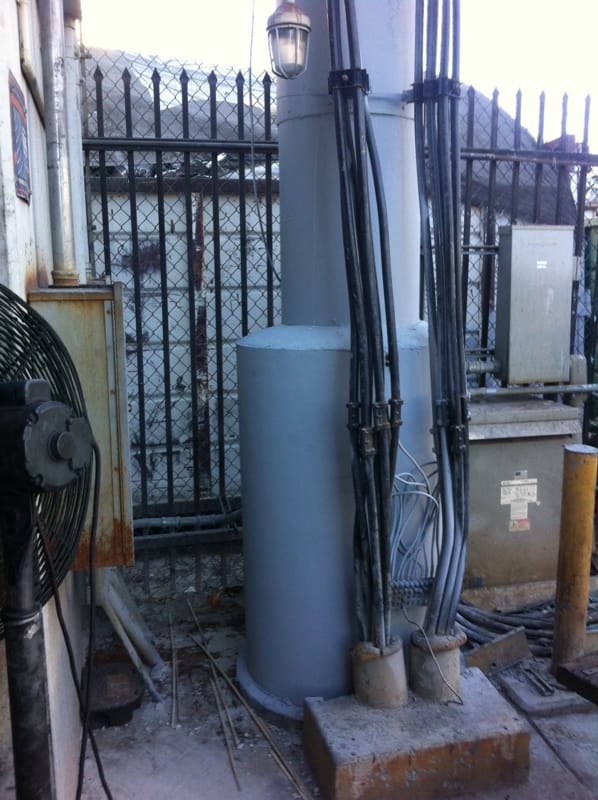
Near the base of the pole, the moments had to be transferred into the footing. Since the carbon FRP is terminated at this location, steel reinforcement was used to achieve this objective. The FRP fabric in that region was coated with a layer of sand for improved bond and to transfer stresses. Twelve No. 8 Grade 60 bars each 14 ft (4.3 m) long were epoxy anchored into the existing foundation. These bars extended 4 ft (1.2 m) above grade (Fig. 6). Even though a 4 in (102 mm) annular space was sufficient, the existing square steel base plates required the shell to have a diameter of 25.75 in (654 mm) at the base. As can be seen in Fig. 2, this resulted in a very conservative over design near the base of the pole. The completed repair of the base region was just wide enough to fit in the available space between the existing cables and the fence wall (Fig. 6).
Field Installation
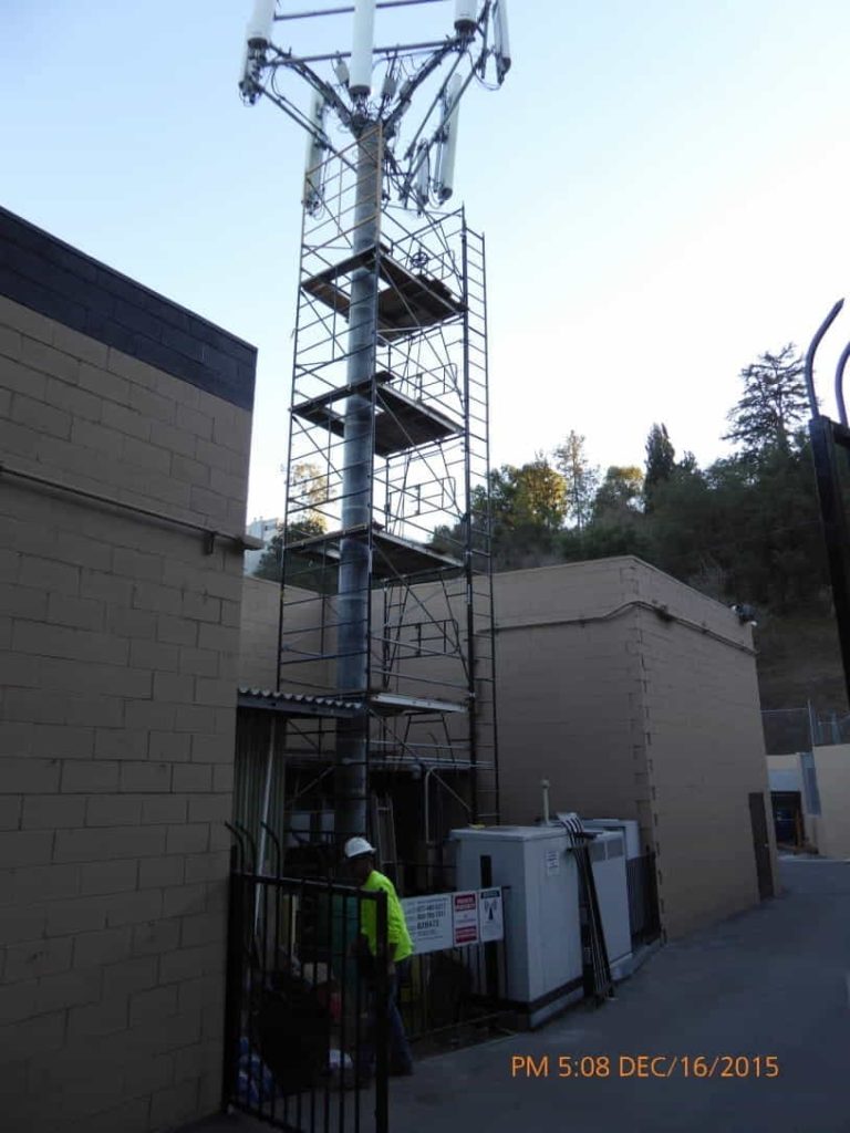
The strengthening solution presented above took approximately four days to be completed. The lightweight laminates eliminated the need for heavy equipment and all work was accomplished using a manlift (Fig. 1) or scaffolding (Fig. 7). Once the shells were created around the pole, the annular space was filled with a high-strength non-shrink grout. The laminates were coated with a UV-resistant coating. Many cables and appurtenances that were near or attached to the pole were moved slightly to accommodate the FRP and concrete placement, and were then relocated to their original position (Fig. 6). The design allowed the pole to remain fully operational during the repair with little change in the appearance and size of the pole.
Fifty-two (52) monopoles have been retrofitted with this technique in 2015 and 2016. Additional structures have been scheduled for retrofit in the greater Los Angeles basin and elsewhere for 2017 based on cell phone coverage needs.
